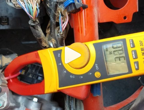
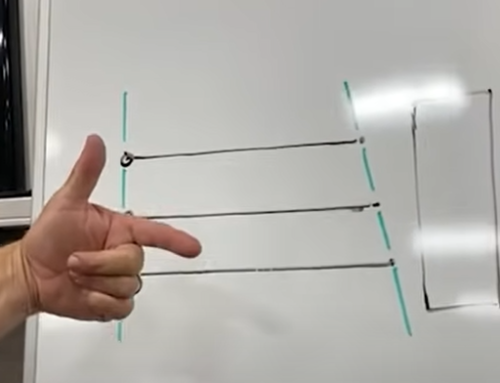
The EPS Controller can be tested with a multimeter. The controller has two wires in the plug, a white and a brown wire. The instructions to test both the brown (relay power) and white (digital signal) are provided below.
Video Tutorial:
Written Instructions:
The instructions to test your EPS Controller are listed below:
Tools:
- 30 amp DC Power Source
- Multimeter
- Aligator clip testing cables
- ECU Controller
Step 1: Wire the hot (red) and ground (black) to a 30 amp power source
Step 2: Wire the Black probe from the multimeter onto the ground. So the grounded wires should include the probe from the multimeter, the black wire from the controller, and the aligator clip connected to the amp.
Step 3: We are going to use the red probe from the multimeter to test the wires inside the clip on the controller to determine functionality.
Step 4: Turn on the amp. Find where the box shows volts and amps. The volts are going to show how much power is going into the controller.
Step 5: Set your power source on your amp to 13 volts.
Step 6: Set your multimeter to 12 volts DC.
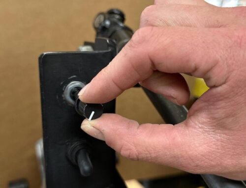
Step 7: Turn the adjustment knob counterclockwise to show that it is turned completely off.
Step 8: Open back of plug by wedging a small screwdriver or the tip of the probe into the teeth of the clip and carefully lift the clip.
Step 9: Touch the red hot probe to the brown wire. The multimeter should show 0.
Step 10: Now turn the knob clockwise to about half way.
Step 11: Probe the brown wire again and the volts should be around 13v.
Step 12: Probe the white wire and the multimeter should read around .6 to .9 volts.
Step 13: Feel free to repeat the test again by turning the knob from off to on and watching the numbers on your multimeter to be sure of the read.
You have successfully tested your EPS Controller.

